Technical Specifications

Technical Specifications


 General Features:

  • Inputs can be made graphically, with spreadsheets or via DXF. All model data is stored in spreadsheets that can be accessed at any time. Changes made graphically are instantly made in the spreadsheets and vice versa. You can also import model from one VersaFrame file to another.
  • Fully Integrated concrete and steel design; see details below.
  • Powerful editing features such as undo/redo, duplicate, array, move, scale, delete, revolve, extrude, beam split, nodes at intersections, sub-mesh shells, node and element merging, explode members at nodes, automated orphan node removal, freeze except plane and freeze except level.
  • In addition to the industry standard 64-bit solver, VersaFrame offers a 128-bit solver that provides unmatched precision and reliability for numerically ‘tough’ structures.
  • Ultra fast and efficient sparse matrix solver in addition to traditional skyline solver. The sparse matrix solver can be configured for parallel processors/cores and restricted RAM access.
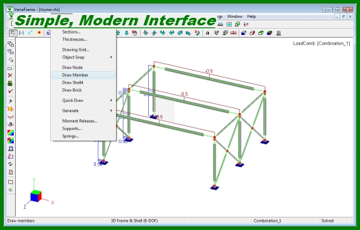
  • CAD-quality graphical interface (OpenGL) supports real-time pan, zoom and rotate as well as Window, Pick and Cross selection methods. Additional CAD-style utilities include drawing cues and member object snaps.
  • Visualization tools such as to-scale graphic rendering and the ability to freeze/thaw parts of a model make editing and viewing large/complex models enjoyable.
  • Command Line Input – this optional feature is for those familiar with AutoCAD. Just like AutoCAD, you can key- in commands, input and set up aliases for commands.
  • Quick Draw – abbreviated drawing commands specifically designed for ultra-quick command line based geometry creation (members, shells, bricks).
  • Animated shear / moment / deformation diagrams and contour plots clearly illustrate structural response.
  • Input and output can be printed directly from the spreadsheets or in report format. Reports are generated in either plain text or HTML format and include both text and graphics.
  • Multiple document interfaces allows more than one model to be open at the same time—great for making comparisons. Further, each model may have multiple “viewports” allowing the structure to be simultaneously viewed from different angles.
  • Linear and nonlinear (compression only/tension only) springs can be defined at nodes, along members and on surfaces of shell elements—making VersaFrame great for foundation design.
  • Members can also be modeled as tension only or compression only members.
  • Named Selections – this new feature is similar to AutoCAD’s Group feature it allows you to define “assemblies”, which you can select with a single click.
  • Comments – place notes/text in your model great for reminders or expressing ideas to others.

Element Types:

  • 2D/3D frame and truss.
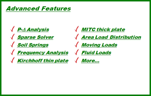
  • 3D, four-node shell element. Includes thick (MITC4) and thin (Kirchhoff) plate bending and plane membrane stress (compatible and incompatible) formulations.
  • 3D eight-node solid element (brick).
  • Rigid diaphragm in regular and generic plane.
  • Rigid Link.

Loading and Boundary Conditions:

  • Static Forces: concentrated, uniform/linear, surface and self-weight.
  • Area Load distribution on Members.
  • Fluid Pressure on shells.
  • Load Patterning.
  • Moving Loads.
  • Rigid supports and frictionless moment releases.
  • Displacement: Support Settlement, Linear and nonlinear (compression only/tension only) spring supports for nodes, members and shells.

Analysis Methods:

  • Static linear.
  • Static P-Delta.
  • Frequency/modal analysis.
  • Sparse and Skyline solvers, with parallel processing on multiple processors/cores and user-defined RAM utilization limits.

Integrated Concrete Design (inside VersaFrame)

  • VersaFrame includes comprehensive concrete design that designs beams, columns (biaxial) and plates-if you can model it, VersaFrame can design it. Key features include:
  • ACI 2002/2005/2008/2011 code.
  • Biaxial column design (round and rectangular).
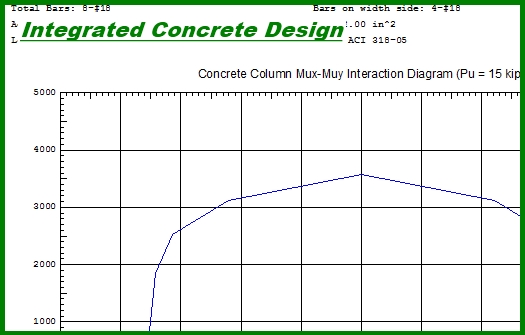
  • Interaction diagrams (columns).
  • Shear design of columns (ties and spirals).
  • Automatic moment magnification.
  • Flexural and shear design of beams.
  • Shear and moment diagrams, including capacity curves.
  • Cracking factor input to automatically reduce section properties for analysis (beams and columns).
  • Automatic determination of member offsets from supporting members (beams).
  • Design of plate/shell structures using Wood-Armer moments.
  • Reinforcement contour plots for plate/shells and member capacity utilization color coded plots.
  • Spread Sheet format allows you to quickly sort and compare design and code check results for members.

Integrated Steel Design (inside VersaFrame)

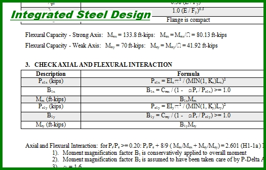
This is the most detailed steel design software available. That is not an exaggeration it’s a fact. No other program provides the level of detail available from Digital Canal. Steel design checks and designs are in accordance with AISC 14th Edition, AISC 13th Edition, ASD 9, and LRFD2 standards. In addition to standard detailed and summary reports, reports can include a step-by-step listing of the computations used to design the member. The program displays each equation and the resulting calculated value for each step of the design process. These incredibly detailed reports are created in Microsoft Word format (RTF).

Steel Design Technical Specifications:

  • Supported sections include I-shapes, channels, angles, double angles, tubes, pipes and tees.
  • Element’s can be checked and designed for deflection criteria. Separate load combinations can be specified for live and total load deflections. Additional design constraints such as depth limits can also be specified.
  • Elements can be colored according their code check status; a five-color spectrum visually indicates their stress level.
  • Spread Sheet format allows you to quickly sort and compare design and code check results for members.
  • Versatile environment. The program utilizes spreadsheets for entering input and viewing output. These spreadsheets are compatible with Microsoft Excel and entries can be copied and pasted between the two applications. Reports are generated using RTF format, which is native to Microsoft Word. In fact, the reports are automatically displayed in Microsoft Word or Word Viewer. Note that reports can be viewed using any word processor that reads RTF files, which includes almost all word processing programs.
  • Element cross sections can be automatically updated (in the model) by the steel design routine allowing for quick and efficient design-analysis cycles.
  • Conditional allowable stress increases for wind loading. User can define relationship between load combinations such that the 4/3 increase factor for a combination containing wind loads is only used if the combination without wind does not exceed allowable stresses as given by 11th Edition ASD.
  • Procedure Reports are reports that step through the complete code checking process, listing every computation made including the equation used, computed value and reference in the code book. This unique feature is only available through Digital Canal. It is an invaluable tool for engineers for verifying steel code check calculations.
  • Output includes: allowable stresses/ultimate strengths, critical stresses/section forces, deflections and deflection ratios, ratios for each stress/force component, locations of critical sections, optimal shape recommendations and detailed computation procedures.